Steve Litt's Summer 05 Intro to Physical Computing Journal


Sunday July 3, Week 1 Lab 2

I was pleased when got my program in which 8 leds light up one after another to work without any real difficulty at first, but after running through the cycle a few times, then turning it off and back on i found that every light lit up at once and stayed on. I was certain that this couldn't have anything to do with my code and that there was some kind of electrical issue going on. Tom pointed out that i didn't have a resistor, or any connection at all, from the input switch to ground. This resistor is apparently necessary to get rid of excess voltage, so that it has somewhere to go when the switch is open. Also, the book says that there can be 'stray' voltage: static electricity, radio waves, etc. which can affect the circuit if the resistor to ground in not in place.


Wednesday July 6, Week 2 Lab 1

I fried my second PIC today, rather carelessly putting it in the wrong set of holes in the breadboard and thus sending the power to all the wrong places. It was very hot when i pulled it out.

I still haven't come up with any particularly striking ideas for a big project, although i had two or three thoughts which may or may not develop into something interesting:

1) applying sensors of some kind to a drawing program. I took Code & Me last semester with Amit Pitaru and built a drawing program using Processing which i like very much and which i'm continuing to add to. obviously, i could apply just about any kind of sensor to it, but it's very difficult to come up with one in which the user's motion/interaction is used in a very specific, meaningful, and unique way.

2) The idea of misusing or finding glitches within pieces of hardware or software is of great interest to me and i find that my favorite works of my own are those of these 'controlled mistakes'. During this past Spring semester I took a computer animation class which taught Maya. At around the same time that i was growing frustrated by how everything everyone made, no matter how thoughtful or well done the work was, had exactly the same visual style, that "this was obviously made with Maya" look, I discovered very visually rich and controllable glitches which created great flickering, semi-random bursts of color could be made by placing objects directly on top of each other. I ended up using or basing all my work for the rest of the semester on this.

So I'd like to come up with something which intentionally misuses or destroys the physical piece/apparatus itself. i would definitely be interested in making a far less extreme version of a piece like Chris Burden's Samson in which any act of participation in the piece is actually slowly destroying or mutilating it in a somewhat unpredictable manner. Maybe something which will intentionally fry a bunch of leds or lightbulbs in some meaningful way. maybe slowly melting some thing or things.


Wednesday July 6, Week 2 Lab 2

code

I tested my photocell and found it was giving me a range of about 400 to 900, so i normalized the values of my pulsewidth to respond with 50 to 250 in response to my 400 to 900. i found that when i would completely cover the photocell the motor and the light would go from superfast, almost unseeable pulsing to pulsing very slowly, at somewhere between once every second and half second the motor would also go from not moving to making a jerky motion in time with the light's pulse. not what i wanted. i eventually realized this was happening when the value of ADCvar was lower that 400, making the pulseWidth variable a negative number. I'm not sure why this caused the slow pulses that it did. Being that it the value was dipping only a few numbers below 400 i decided to add an if statement so that the motor and light only pulsed if ADCvar was over 400. 


Week 3 Labs

processing code basic code

In addition the basics of serial input and output this week I decided to teach myself a bit about bringing live video input from my dv camera into processing. Anyone interested should check out the processing video library for coding info, and download Win VDIG, which will convert your live video feed into Quicktime format so that processing can use it. It's surprisingly simple if you can do the basics of serial in and out.

The code above is for my first movie-to-pic program. when the user start the program it shows the streaming video. when the user clicks anywhere in the program's window it:

1) finds the average color of the pixels in the center of the screen (there is a black rectangle drawn there to denote this space),

2) finds whether the average color in the rectangled area is red, green, yellow, or none of the above (as defined by a set of red, green, and blue values which i give it), and

3) sends this info out the serial port to the pic chip. the pic turns on the appropriate red, green, or yellow led (and turns off the others) if there is a color match, or turns all of them off if there isn't one.

i'm pleased that i got this to work with very little difficulty. now to try to think of some more interesting uses for it.


Week 4 Midterm Project: Three Walkman Tape Loop Manipulator

code

Part I: Brainstorming, Ideas, Etc.

My midterm project came about more or less because of my hearing and reading about way to many musicians and artists who i enjoy using various forms of tape loops and tape manipulations to achieve a huge variety of interesting musical and artistic ends (if you're interested, i highly recommend William Basinski's The Disintegration Loops and anything done by the creators of Frippertronics). the sounds one can get from analog devices such as magnetic tape can be, at least in my opinion, far richer (if less 'clean' or 'clear' sounding) than those which one currently get with midi, digital samplers, or with even the most high-end digital synths.

One of the coolest use of tapes is the tape loop, in which a short piece of magnetic tape is attached at its ends and put into a tape player, thus playing the same little bit of recorded sound over and over. The invention of the tape loop was, i believe, some time around the 1950s, and was used by adventurous composers (Riech, Stockhausen), before notable pop and rock musicians really started to play with them in the 60s and 70s. They were (and generally still are) made using very expensive reel-to-reel tape recording machines which use tapes bigger and more expensive than a cassette. For a more thorough explanation you can check out the Wikipedia entry.

So i thought the tape loop was out of reach until i realized i could probably do the exact same thing on a walkman or a standard cassette player. 5 dollar walkmen at Kmart sealed the deal and i bought three.

There were a whole bunch of different ideas i had about how to manipulate them:

1) Manipulate the walkmen themselves.

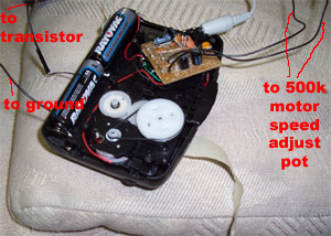
Opening one up i immediately saw two of those little mini circuit-board sized pots you turn with a mini screwdriver. one had the volume knob attached to it, no need to ask any questions there. a volume knob for the user would certainly be nice. the other one i found was connected to the motor and could significantly speed up and slow down the motor. i figured a bigger pot would make the speed change even more dramatic and that this would definitely be a worthy feature for the device. while poking around i also found that connecting two otherwise disconnected points on the circuit board with a wire would add an interesting sort of fuzz/distortion effect (strangely i have not been able to find this set of points ever since, otherwise i would have included this).

2) Do all kinds of other stuff with the Pic i.e. stuttering on-offs, sequences, and pulsewidth-modulation.

Without the pic all i would be able to do is turn on and off each player individually and manipulate the volume and speed. The first and, i think, best thing that came to mind to use the Pic for was to play the three, or any two, in a sequence. what i mean by this is to play one for a set period of time, as set by a pot to the Pic's analog input, then stop it and begin the next one. it could move between either three or any two of the walkmen depending on which switches the user had turned on at the moment. I decided i would make this work, then see what could be done with PWM, not being entirely sure what the result of dozens of on-offs every second would be.

Part II: Assembly, Programming, Etc.

Easiest things first. The night i bought the walkmen and took them apart i desoldered the mini motor-controlling pots and replaced them with normal sized 500k pots, which created a pretty dramatic increase in pitch/speed change from the original pots.


Next, programming. The first thing i did was program switches to the Pic that would turn each walkman on and off. so i went to radio shack and bought a thing of 15 PNP (normally open) transistors. i got back to the lab and tried one out and it would not turn the walkman on, although it would turn an LED on. i asked Tom if he had any idea why it wasn't working and he pointed out the back of the transistor's box said they had a maximum current of 0.8 amps. we couldn't find any info on the walkman or its box on its amperage but assumed this was the cause. Tom brought back a higher current transistor, a TIP120, and my switch-to-walkman setup magically worked. so i went back to radio shack and bought 2 of the highest current transistors they had, TIP31s, which can take a maximum of 3.0 amps. so i set up the other two walkmen to the Pic as i had the first.

seems like it would be simple enough from here, but i got some pretty odd difficulties which i was not able to fix. in short, only two would turn on at a time. when i turned the third one on, it would stop all three and give a quite unpleasant high pitched screech. sometimes when i would turn just two on it would play them both but play one at a much lower volume with a similar high pitched noise on top. i moved around the transistors going to each walkman, thinking maybe one or two were broken or partially broken, then bought different transistors, then moved them all around again but still had the same problem. so i moved on to sequencing and pushed this part aside for the time being.

there has got to be a better way to program the sequencer than the way i did it, but it worked so i figured i would leave it alone. in short i made an if-then statement for every possible combination of the three on/off switches, which took a few too many lines of code. but the sequencer worked right away just how i had wanted, and without any of the noise or volume trouble i was getting before.

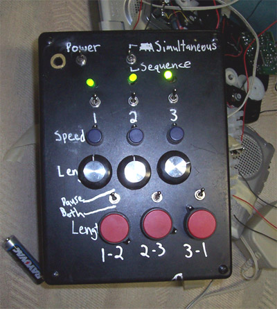
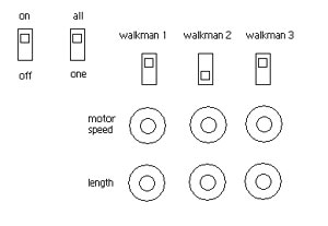
the last thing i added was the switch to go between the All-at-Once and One-at-a-Time mode. then i hastily stuffed it into the bottom half of big ugly cardboard box which i figured would do the trick for the time being, then labeled the switches and knobs without giving much though to whether the labels would make any sense to a random user.


Making tape loops

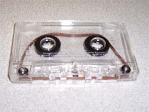
Somewhere in the middle of this process i made a bunch of tape loops by ripping the tape out of old cassettes and replacing it with homemade loops. be forewarned before trying this: you have to get just the right amount of glue on the ends of the tape. after about 10 tapes i still have not mastered this. too much and the glued part will get stuck in the walkman's tape-pulling-along mechanism and completely stop, too little and the ends will rip apart and get eaten by said mechanism. it also helps if the length of the tape is just the right size to fit snug-ly around the empty cassettes wheels, or whatever they're called. but once you get them right it makes it all worthwhile, and if you have a tape recorder you can record your favorite 3-4 second bits of your favorite records by holding it up to your stereo as i did. really quite exciting, it ultimately gives a whole new meaning and life to an arrangement of sounds/voices/instruments to hear them cut out of a normal piece of music and repeated ad nauseum, slightly off beat. my technique so far has been to just record random bits of records which i like and throw two or three together to see how they sound together, but i think at some point im going to try to get a different instrument on each tape, or maybe take three different instruments from different parts of the same song and listen to the disjointed version that results.


Week 6 Final Project: Improved Walkman Tape Loop Machine


code

mp3 sequence function played through distortion pedal

My final project was an improved version of the walkman looper. These are the improvements I made:

1) fix the Simultaneous function so that all three walkmen can be played at once.

My 3 outputs to walkman: one was on port C, the other two were on port D. At some point I realized that having both pins on port D on at a time was creating the problems. i moved one to port B and everything suddenly worked! whew. later i asked Tom what this was about and he figured that port D probably has some sort of special function which was causing my problem. we looked it up in the Pic 18F4XX info book and found this was in fact the case. aparently when one pin on D is turned on the others on D are affected in a way which for me was undesirable, automatically turning them on or off in response to any one being turned on. there is a one line statement which you can add to the beginning of your program to turn this special function off, but i had already more or less fixed the problem by moving the output to a different register so there was really no need. i wish i had looked in the book sooner.

2) add LEDs which turn on and off as each walkman is turned on and off.

Although very simple, this ultimately makes the device much, much easier to learn/figure out for someone who doesn't know how it works. Otherwise it could be very difficult for the user to identify how the knobs and switches relate to the sounds being produced. Even for me, knowing as well as anyone how it works the lights make using the device much more pleasant.

3) add a new function which allows one to set the amount of time between each walkman is played, during which there is either a pause or both walkmen on at once.

Added 3 more analog inputs, one for the space between walkmans 1 and 2, one for 2 and 3, and one for 3 to 1. then 3 switches, one to be put above each one. if a switch is on/up, it makes a silent pause for the amount of time set by the analog input between the appropriate two walkmen. if it is off/down, it turns on both walkmen for a period of time according to the same analog input.

4) put it all in a nice box of some sort

I found on of those black plastic radioshack boxes on the junk shelf, its dimensions about 8"x6"x3". it looked nice enough and i figured it was about as good as anything i would find, so i decided to use it.

This was the only really frustrating part of the project, for two reasons. first because i had to fit 8 switches, 4 leds and 9 pots on one side, with the breadboard inside, which would have been a challenge anyway, but the wires i had going to the switches and pots were so short that i had to reach under the top half of the box, hardly able to see anything in there as i put them in place while being very careful not to pull any of the many, many other wires on the breadboard out. One lesson learned here: when you have millions of wires to deal with, use really thin wire than can be bent and moved around easily. that way you can make it as long as you want and then just tie it up and stick it somewhere out of the way at the end.

The second problem with the box: after i got it all in there it worked for about a half hour, then one of the walkmen started turning on whether i had it switched on or not, then it completely stopped working and i couldn't even get an LED to light up. i put a new voltage regulator in and looked for disconnected wires but to no avail. i stared at it for about an hour and tried taking things out and putting them back in but to no avail.

I gave up and came back the next day. still didn't work. so i took every switch and pot off the box and tried again. everything worked perfectly. don't ask me why but it did. i decided that it would be a good idea to put everything back on the case while it was turned on so i would be able to pinpoint at what point something went wrong, if it did. fortunately nothing went wrong and i got it up and working about an hour before class started, which gave me just enough time to label the controls with a silver paint pen and draw some kickass graphics on the side of the box.

Future Plans for this device:

1) plug it into some guitar pedals, namely metal destortion and delay.

2) add volume control.

3) find that distortion thing i mentioned earlier.